Line 6 DT 25 Bias
The valves from my amp where giving me problems the amp had crackling noise and spikes in the volume.
Valves with time decay until they fail, so ordered new valves to replace the old ones, 2 EL84 and 1 12AX7.
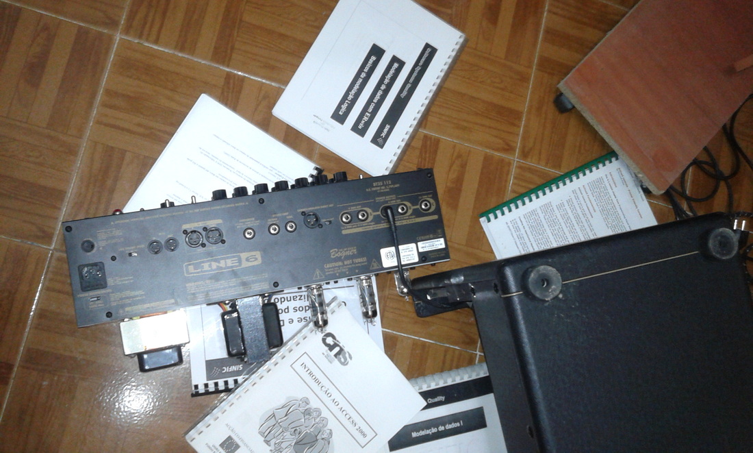
Changing the valves requires taking the head out off the cab.
Valves with time decay until they fail, so ordered new valves to replace the old ones, 2 EL84 and 1 12AX7.
Changing the valves requires taking the head out off the cab.
That image is not focused… but after reading a bit off the process in the Line 6 forums and checking some videos on how to bias an amp i had the basic information needed to a do this task, witch is a dangerous task…
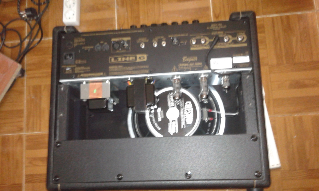
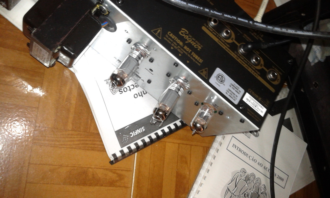
The Head needs to be removed from the cab, in this photo i already had taken the top board that covers the transformers and valves, its a board like the one in the bottom off the amp, its attached by 4 screws, keep in mind that if the amp was never taken apart there a small amount of glue also, you have to gently pull the board until the glue can no longer hold the board.
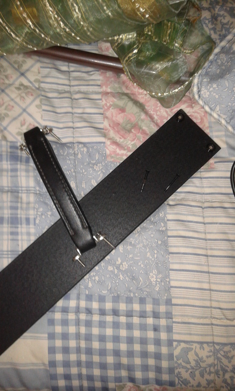
Next you need to remove the 2 screws in the top off that amp, next you need to remove the 4 screws on the handle, the handle screws are 2 sizes, when you place the head back you need to place the short screws in one part and the longer in the other, the holes are different in depth so the long screws can not fit in the shot holes.
The Head needs to be removed from the cab, in this photo i already had taken the top board that covers the transformers and valves, its a board like the one in the bottom off the amp, its attached by 4 screws, keep in mind that if the amp was never taken apart there a small amount of glue also, you have to gently pull the board until the glue can no longer hold the board.
Next you need to remove the 2 screws in the top off that amp, next you need to remove the 4 screws on the handle, the handle screws are 2 sizes, when you place the head back you need to place the short screws in one part and the longer in the other, the holes are different in depth so the long screws can not fit in the shot holes.
To remove the head its easier if the amp is placed up side down, it slides better this way, also there’s also some glue witch needs to be broken.
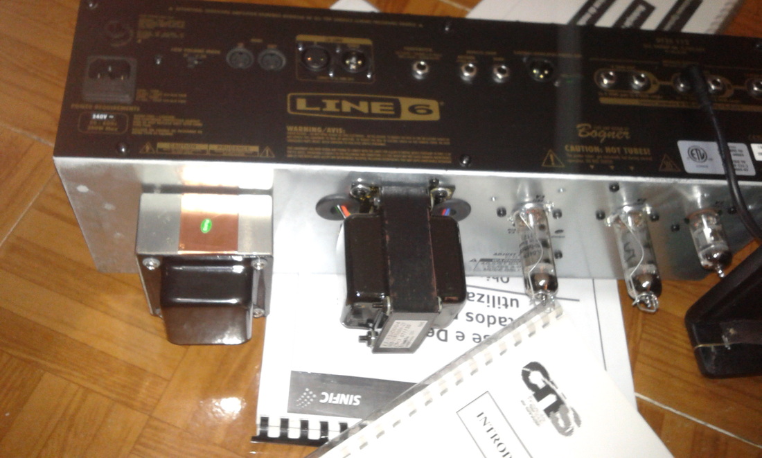
The section where the transformers and valves are is more heavy, so you need to be carefully when placing it outside the amp.
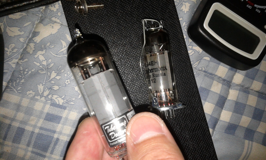
News tubes to replace the old ones, there’s 2 EL84 witch have that spring and metal plate to screw in to amp, the spring slides like a leaver so that you can remove the valve from and place the new in. Removing and placing the tubes (both the EL84 and the 12ax7) requires to slightly rock the tube in the socket and pushing/puling at the same time you are rocking the tube. The EL84 spring system can be rotated to match the holes where it screws in to.
Now its time for the dangerous part, the one where you can be shocked….to death in worst cases.
Adjusting the voltage values that the valves operates requires having the amp turned on, you need to have the speaker connected to the amp.
Now its time for the dangerous part, the one where you can be shocked….to death in worst cases.
Adjusting the voltage values that the valves operates requires having the amp turned on, you need to have the speaker connected to the amp.
The amp needs to be in Class A/B for bias.
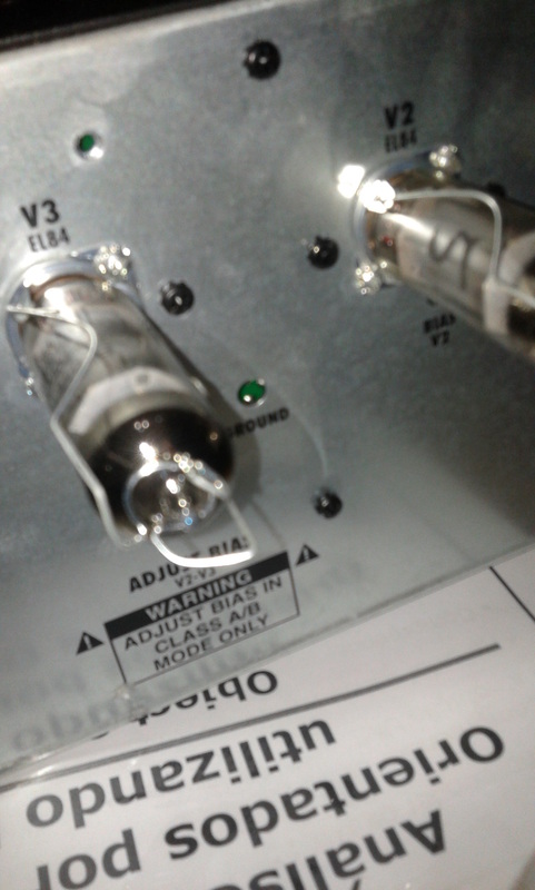
Next you need to use voltage meter (set to 200), i had to try a couple off times to get it right. There’s a V2 and V3 holes to measure the voltage, you need to connect the voltage meter prongs 1 to the V2/V3 and the other to the ground and check the voltages for each valve, the reference value is 25 plus or minus 3 is in acceptable values, so for example V2 can be to 22 and V3 to 28 witch is still in acceptable range. To adjust the voltages you need to have the voltage meter measuring the hard part is the prongs staying in the proper position to measure, the measure point is small and the prongs can move, to adjust the voltage that the valves receive the bias button needs to be adjusted this will change how much both valves are receiving, that button is very small also and since you need to use a small screw driver there’s not a lot off feedback from moving the button, and the changes needed to be very small. Small button means any tiny adjustment means a lot in terms off value. I set the bias to 25/26.
While you are adjusting the bias, the amp is turned on witch means there’s deadly voltage in there, avoid touching any thing, and don’t use 2 hand to touch the amp, and the tubes get hot also, so be careful. While i was measuring the voltages even without being in direct contact with the amp it self, just the voltage meter you do feel the voltage a bit.
Then is powering off and carefully install the head back in the cab and test the amp. I think it now sounds better than new.
Then is powering off and carefully install the head back in the cab and test the amp. I think it now sounds better than new.