Page 6
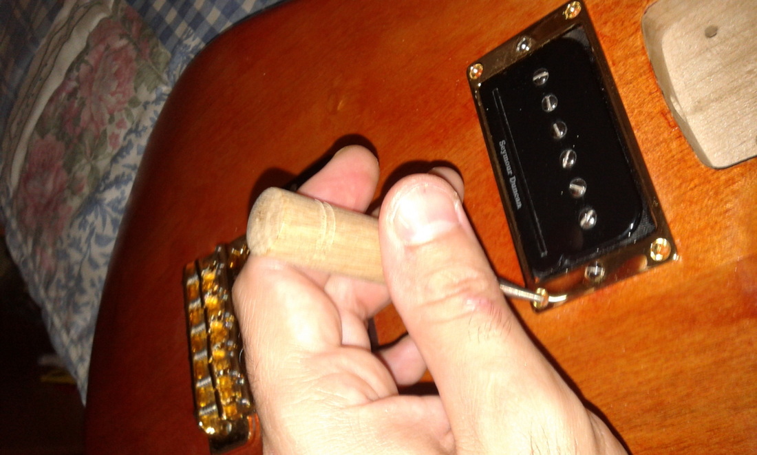
Finally bolted the pickups and bride to the body.
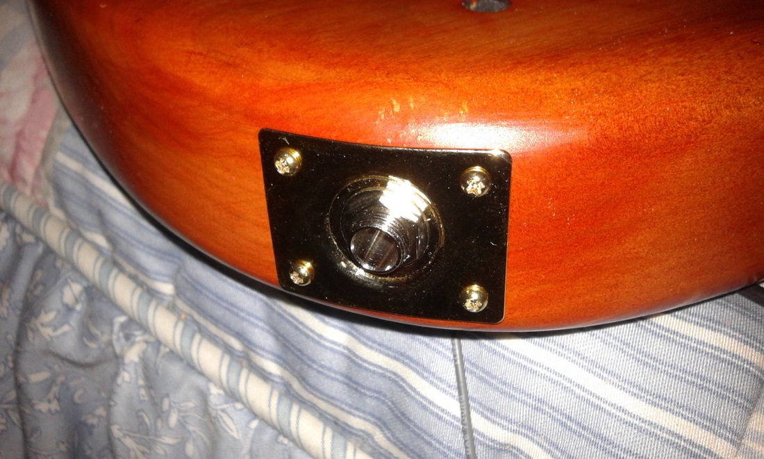
The input jack hole was to small it could not even put the input jack in there. It needs a 20mm hole for the jack and plate, but since the original hole is small and i could not find normal wood drills off that dimension in the store near me i had to get the largest one available.
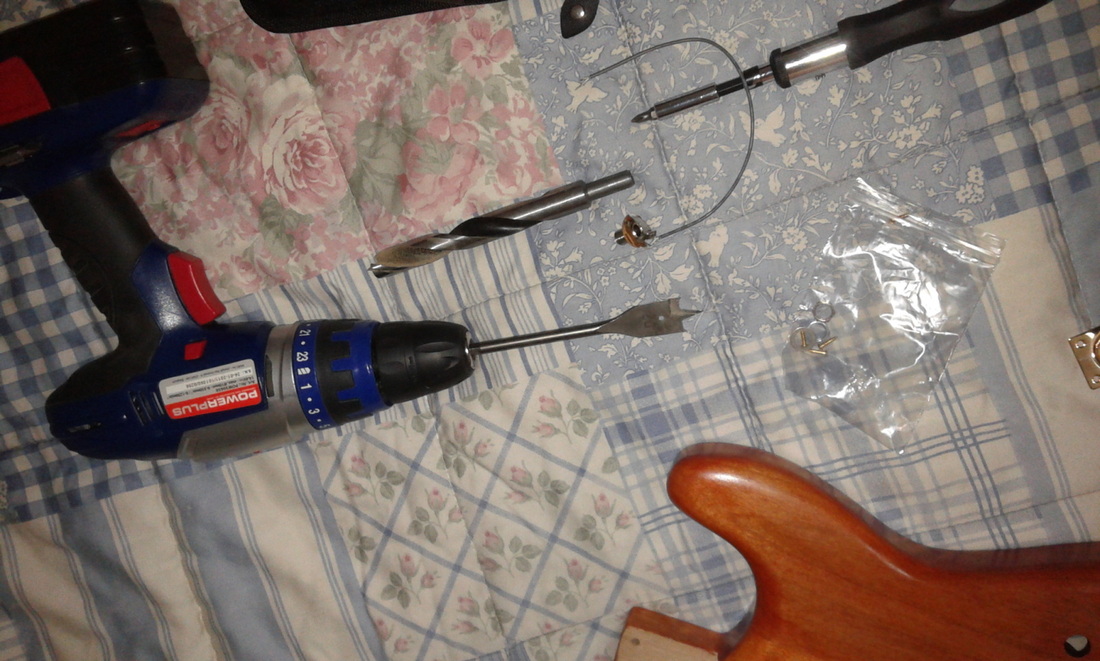
Big drills, very big, the normal bit was used to enlarge the hole, rotating the drill inside the hole to make a larger hole than the drill, finally the other drill witch is 20mm could finally fit in the partly in the hole so that i could drill it to the final size, this drill needs either wood where the center point can fixate or a hole that has the size off the drill, its near impossible to enlarge the hole using the same technique i used with the standard drill.
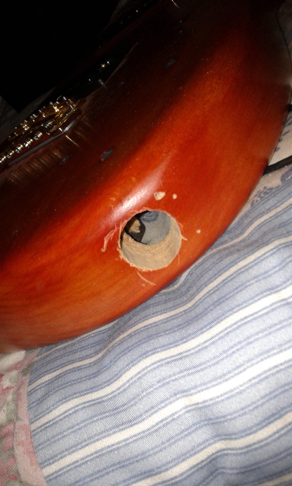
Those scratches where made by attempting to drill with the 20mm drill, that section is covered by the input jack plate, so no problem.
I also manage to damage slightly the control cavity, initially i enlarged the hole with a half round rasp.
I also manage to damage slightly the control cavity, initially i enlarged the hole with a half round rasp.
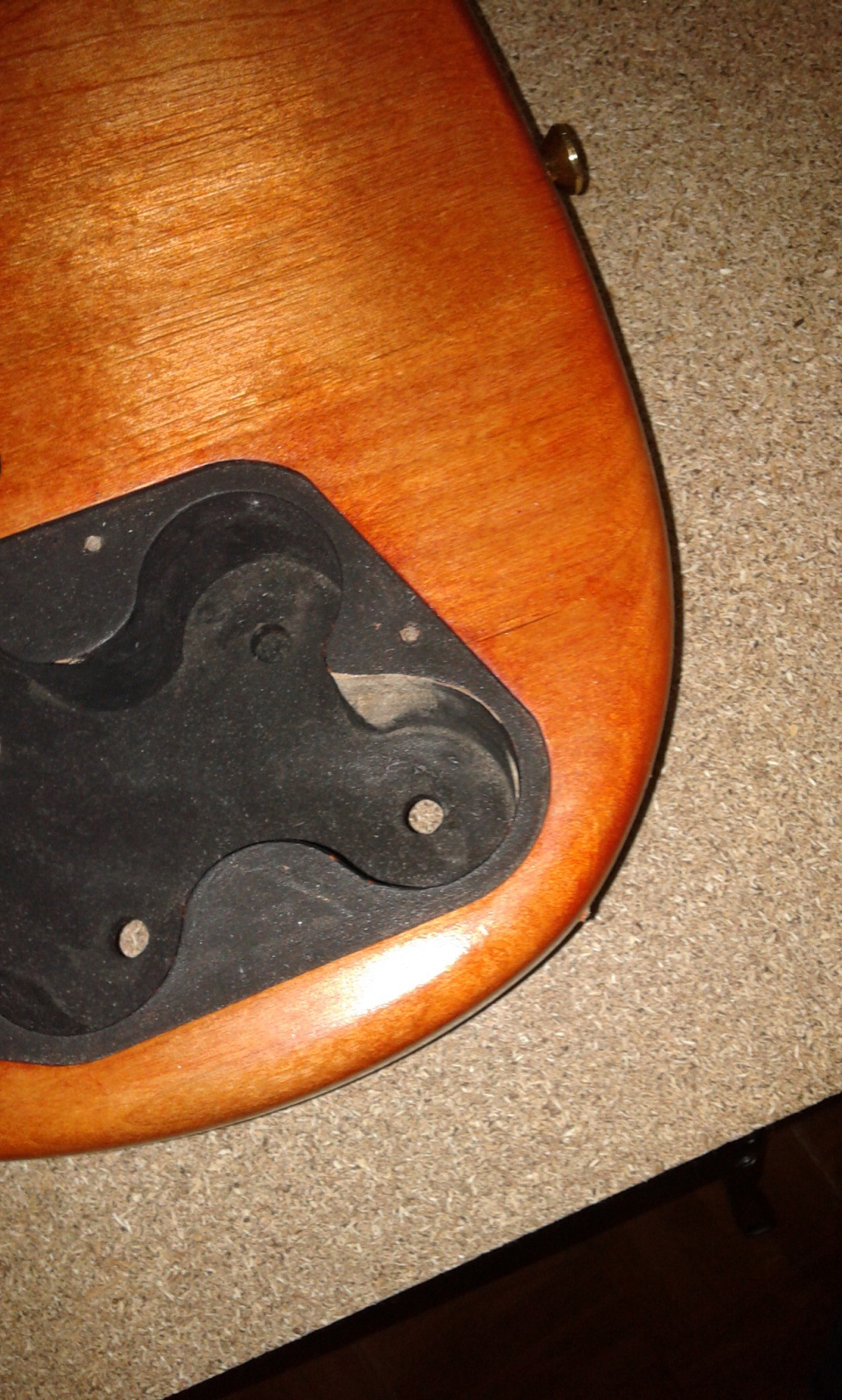
That section had to be fixed. And finally painted again.
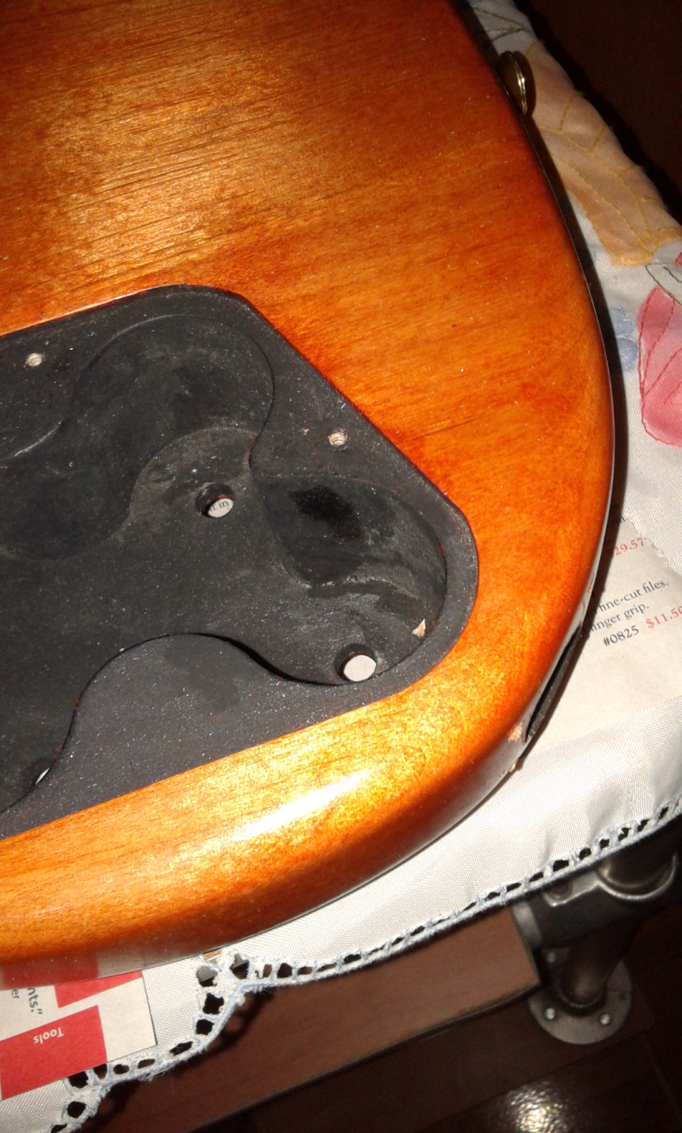
The plate covers the scratches made by the enlarge attempt.
My original idea for the control layout was to have the volume pots in one row and the tone pots in an other row, i changed it for the normal used one volume and tone for neck in on row, and an other row for the volume and tone for the bridge in an other row, i think its better for cables.
My original idea for the control layout was to have the volume pots in one row and the tone pots in an other row, i changed it for the normal used one volume and tone for neck in on row, and an other row for the volume and tone for the bridge in an other row, i think its better for cables.
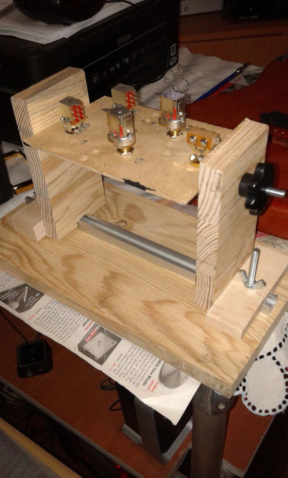
I decided to make a jig based on this one http://makerplane.org/?p=1311, i still did not finish it still needs some a method to clamp the surface where you soldering, at the moment it just sits on top off some nuts, the force off the sides is enough to hold it in place and can even pick the hole jig just by the MDF where the pots are placed. This jig is to some off the welding outside off the control cavity, although a large part off the soldering will need to be inside there.
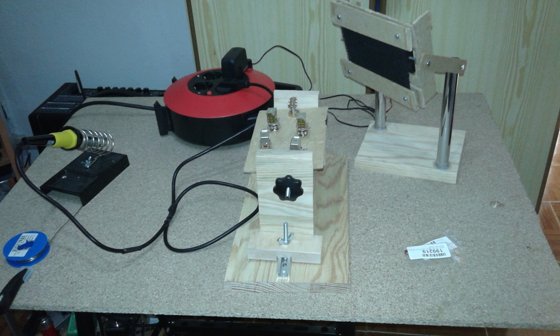
Also made a Frankenstein fume extractor, some wood, some pipes, some old MDF, and old switch, and old PC case Fan 8 Cm, some bolts,some glue, my old router 12V transformer and a eBay Fume extractor filter and its alive. I guess the top section will be redone in an other way in the feature, the bottom off it its OK.
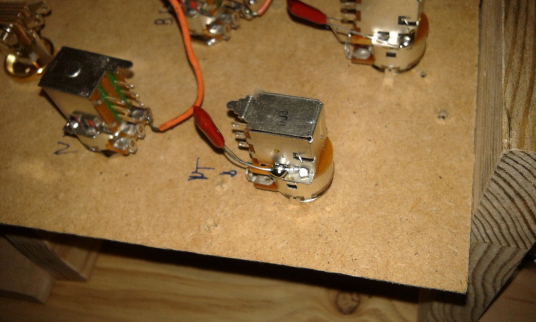
Soldered the 0.47 capacitors and some initial ground wires, the rest has to be done inside the cavity i think.
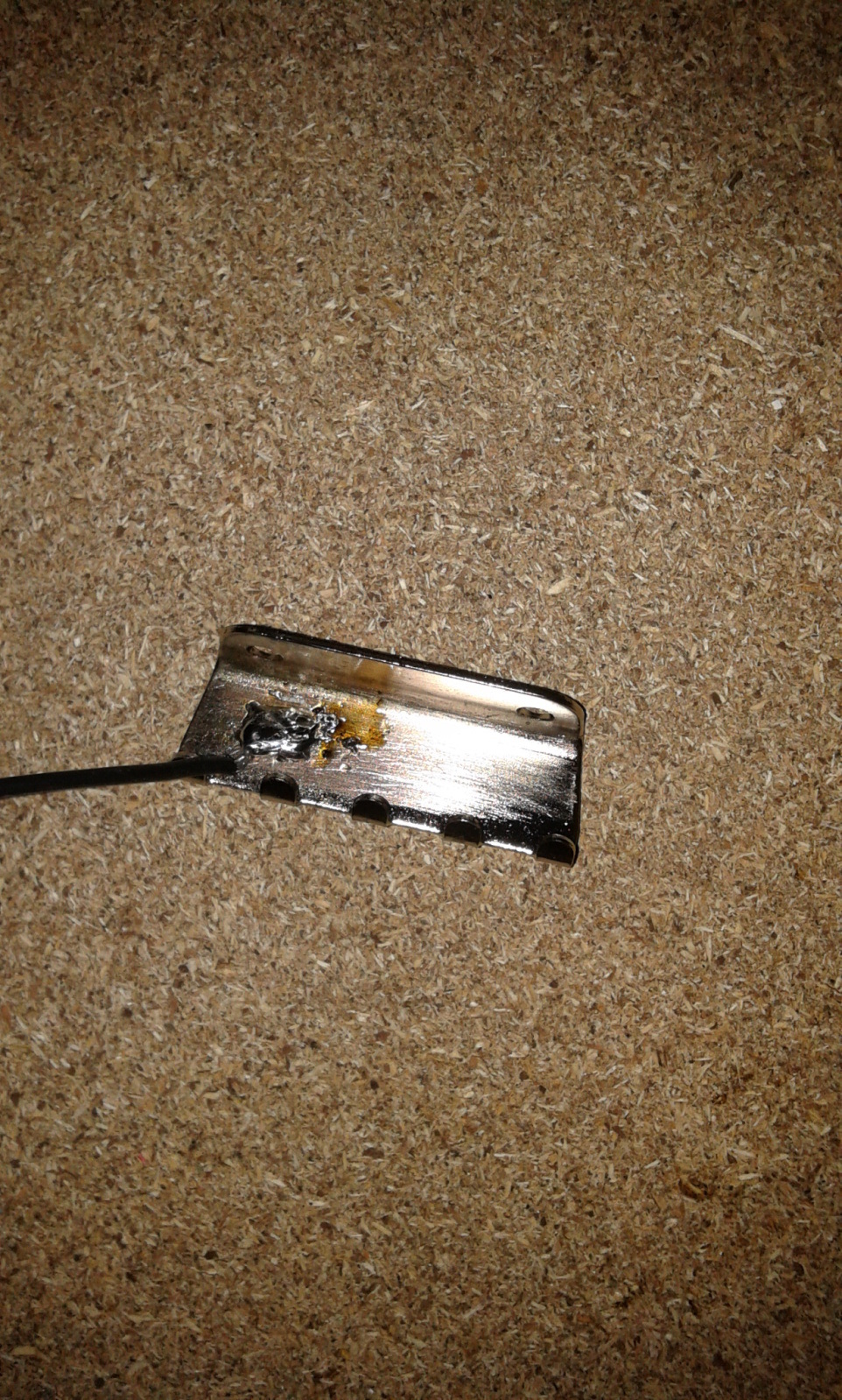
Soldering in large surfaces is problematic for me, i think i took more time to solder the ground for the tremolo claw than the other solders all together. There's a lot off flux in there because off the multiple attempts.
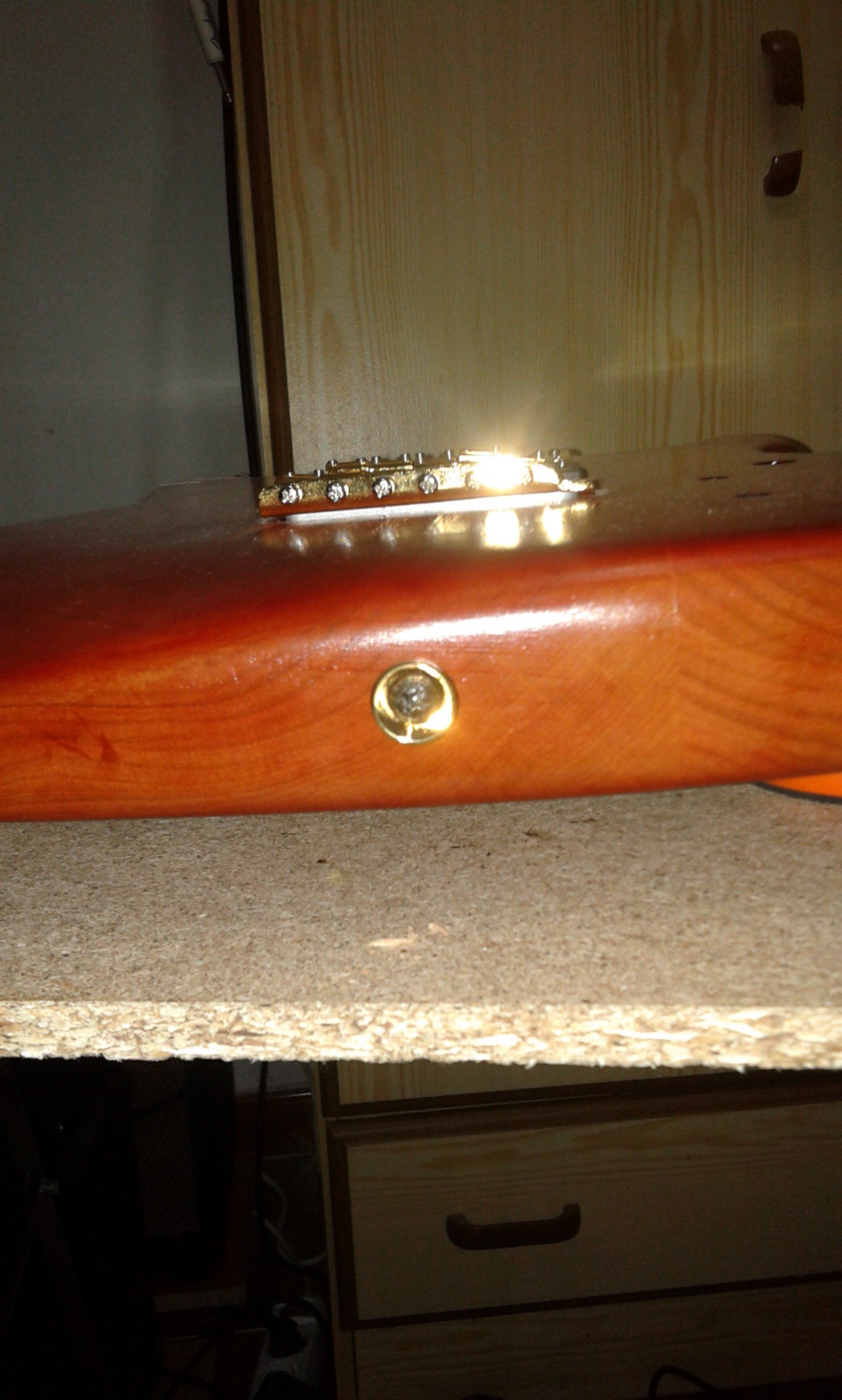
Strap locks also added. I think i am missing something to bold to this guitar, oh yes a neck....
A bit off topic, changed the valves on my DT25 and bias it, still alive. Had to read on line 6 how to take the amp apart, http://happynewguitarday.wordpress.com/2014/07/07/line-6-dt25-bias/ tried to take some pics on the process off how to take the amp apart to take the head off. Now the amp sounds a lot better than new
1st Page - Previous Page - Next Page - Last Page